Part 3: Coding the client ESP8266
Now that we have our server up and running, we can start working on our client. For our client we want to connect to our WiFi, receive a struct from our server over UDP and run our LED strip according to those struct values.
The Libraries
The libraries we’ll be using will be a lot like our server, with the addition of the Adafruit_NeoPixel library which we will be using to control our addressable LED strip.
#include <Adafruit_NeoPixel.h>
#include <ESP8266WiFi.h>
#include <WiFiClient.h>
#include <ESP8266WebServer.h>
#include <ESP8266mDNS.h>
#include <WiFiUDP.h>
#include <ArduinoOTA.h>
We will create another web service, but this time a simple one that only shows that the client is running, we will also be using Arduino OTA again for uploading the sketching, in this example I’ll remove the Arduino OTA code for simplicity, please see part 2 for the Arduino OTA code
Defining our variables
#define N_PIXELS  20  // Number of pixels you are using (you can change this according to your strip)
#define LED_PIN   13  // NeoPixel LED strand is connected to GPIO #13
#define SAMPLES   60
#define TOP       (N_PIXELS + 1)

// Defining our strip
Adafruit_NeoPixel strip = Adafruit_NeoPixel(N_PIXELS, LED_PIN, NEO_GRB + NEO_KHZ800);
// Defining our web server and udp connection
MDNSResponder mdns;
ESP8266WebServer server(80);
WiFiUDP UDP;

// Declaring the struct we will be receiving
struct led_command {
  uint8_t opmode;
  uint32_t data;
  uint8_t red;
  uint8_t green;
  uint8_t blue;
};

struct led_command cmd;

// Defining our html page to return upon request
String page = "<html lang='en'>";

byte
  volCount    = 0,
  peak        = 0,
  red         = 0,
  green       = 0,
  blue        = 0,
  selectableR = 0,
  selectableG = 255,
  selectableB = 0;

int
  vol[SAMPLES],
  lvl         = 10,
  minLvlAvg   = 0,
  maxLvlAvg   = 256,
  soundVal    = 0,
  opMode      = 0,
  ledColCount = 0,
  colCount    = 0;
Most of our variables will be the same as the server accept for our strip and some variables we’ll be using for controlling the strip.
Creating our Setup method
Now let’s implement our setup and loop method
void setup() {
  memset(vol,0,sizeof(int)*SAMPLES);
  strip.begin();

  Serial.begin(115200);

  WiFi.persistent(false);

  page += "<head>";
  page +=   "<meta http-equiv='refresh' content='60' name='viewport' content='width=device-width, initial-scale=1'/>";
  page +=   "<link rel='stylesheet' href='https://maxcdn.bootstrapcdn.com/bootstrap/3.3.7/css/bootstrap.min.css'/>";
  page +=   "<script src='https://ajax.googleapis.com/ajax/libs/jquery/3.1.1/jquery.min.js'></script>";
  page +=   "<script src='https://maxcdn.bootstrapcdn.com/bootstrap/3.3.7/js/bootstrap.min.js'></script>";
  page +=   "<meta name='viewport' content='width=device-width, initial-scale=1'/>";
  page +=   "<title>Reactive LEDs</title>";
  page += "</head>";
  page += "<body>";
  page +=   "<div class='container-fluid'>";
  page +=     "<div class='row'>";
  page +=       "<div class='col-md-12'>";
  page +=         "<div class='jumbotron' style='text-align: center'>";
  page +=           "<h2>Reactive LEDs Client 1 Running</h2>";
  page +=         "</div>";
  page +=       "</div>";
  page +=     "</div>";
  page +=   "</div>";
  page += "</body>";
  page += "</html>";

  connect();
}
Please see part 2 for the connect and disconnect method, it will be the same except for the UDP port and WiFi hostname in the connect method.
WiFi.hostname("node_client_1");
// ...Rest of code

UDP.begin(7001);
The Loop
Now we can start coding the loop, this will be the method that keeps our client alive.
void loop() {
  // Handle client requests
  server.handleClient();

  // Check the current opMode (default is 0)
  if (opMode == 0) {

    // Receive the UDP packets from the server
    int packetSize = UDP.parsePacket();
    if (packetSize)
    {
      UDP.read((char *)&cmd, sizeof(struct led_command));
    }

    soundVal = cmd.data;
    opMode = cmd.opmode;
    selectableR = cmd.red;
    selectableG = cmd.green;
    selectableB = cmd.blue;
    Serial.println("Val received: " + String(soundVal));
    Serial.println("Mode received: " + String(opMode));

    // Run the sound reactive code
    soundReactive();

    // We cna only upload OTA updates on opMode 0
    ArduinoOTA.handle();
  } else if (opMode == 1) {
    strip.show();
    // Run the rainbow cycle code
    rainbowCycle(20);
  } else if (opMode == 2) {
    strip.show();
    CylonBounce(1, 30, 20);
  } else if (opMode == 3) {
    strip.show();
    // Run the meteor rain code
    meteorRain(4, 64, true, 60);
  } else if (opMode == 4) {
    strip.show();
    // Set the strip to a selected RGB color
    setAll();
  } else if (opMode == 5) {
    strip.show();
    // Set the strip to a static white light
    setAll(0,0,0);
  }
}
Running the sound reactive method
This is the method which runs on opMode 0, this will be our default operating mode and will change the LED strip according to the sound level received.
void soundReactive() {
  uint8_t  i;
  uint16_t minLvl, maxLvl;
  int      height;

  lvl = ((lvl * 7) + soundVal) >> 3;    // "Dampened" reading (else looks twitchy)

  // Calculate bar height based on dynamic min/max levels (fixed point):
  height = TOP * (lvl - minLvlAvg) / (long)(maxLvlAvg - minLvlAvg);

  if (height < 0L) {
    height = 0;      // Clip output
  } else if (height > TOP) {
    height = TOP;
  }
  if (height > peak) {
    peak   = height; // Keep 'peak' dot at top
  }

  uint8_t bright = 255;
  strip.setBrightness(bright);    // Set LED brightness

  // Color pixels based on rainbow gradient
  for(i=0; i<N_PIXELS; i++) {
    server.handleClient();
    if(i >= height) {
       strip.setPixelColor(i,   0,   0, 0);
    } else {
       strip.setPixelColor(i,Wheel(map(i,0,strip.numPixels()-1,30,150)));
    }
  }

  strip.show(); // Update strip

  vol[volCount] = soundVal; // Save sample for dynamic leveling
  if (++volCount >= SAMPLES) {
    volCount = 0; // Advance/rollover sample counter
  }

  // Get volume range of prior frames
  minLvl = maxLvl = vol[0];
  for (i=1; i<SAMPLES; i++) {
    server.handleClient();
    if(vol[i] < minLvl) {
      minLvl = vol[i];
    } else if (vol[i] > maxLvl) {
      maxLvl = vol[i];
    }
  }

  if((maxLvl - minLvl) < TOP) maxLvl = minLvl + TOP;
  minLvlAvg = (minLvlAvg * 63 + minLvl) >> 6; // Dampen min/max levels
  maxLvlAvg = (maxLvlAvg * 63 + maxLvl) >> 6; // (fake rolling average)
}
You should now already be able to run a sound reactive LED strip as long as your op mode stays on 0. For simplicity and to shorten the length of this post, see the git project for the rest of the op mode methods https://github.com/zu6fx/sound-reactive-led-strip/tree/master
Conclusion
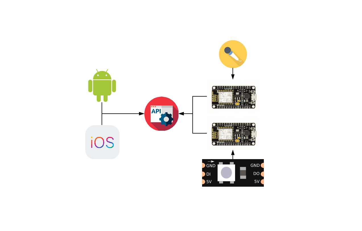
This concludes part 3 of this tutorial. We created 2 ESP8266 circuits and should have both up and running now with sketches. For the final part we will look at creating a mobile application to call the server endpoints and changing the LED strip operating mode. Please continue to part 4 for the mobile application.
Be First to Comment