Today we are building a wireless controlled LED project using two NodeMCU’s with the ESP8266 chip, a sound detection module and a couple of WS2812b addressable LED’s (NeoPixels).
Our goal
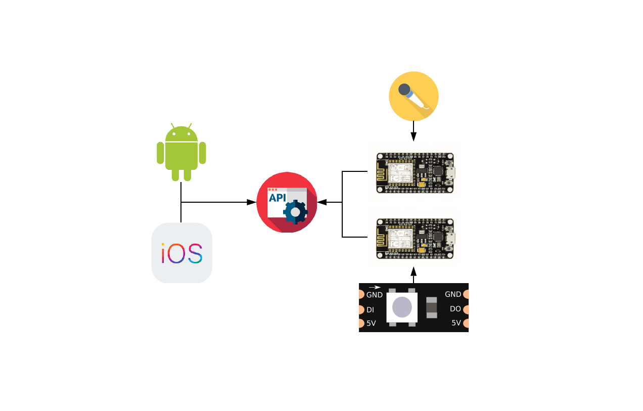
We want to be able to send sound data from one ESP8266 (server) to a second ESP8266 (client) and display the data on our LED strip, we also want to add other effects (rainbow, static and cylon) to our strip which can be customized (effect, color) through a mobile app.
The project is broken up into 4 parts for simplicity. Part 1: Building the circuits, Part 2: Coding, compiling and uploading the server sketch, Part 3: Coding, compiling and uploading the client sketches and Part 4: Building the mobile applications.
Part 1: Building the circuits
To start, here are the parts we’ll need for our 2 circuits:
- 2x – ESP8266 Modules
- 1x – Sound Detection Module
- 1x – WS2812b LED strip (LED count can vary on your preference)
- 1x – Push button (optional)
- 2x – Power supplies, 1 with 3.3v output and 1 with 3.3v and 5v output
- 1x – LED (optional)
The first circuit we will be building, will be our main circuit. It will be handling our web service requests, we can call this our server.
The server circuit:
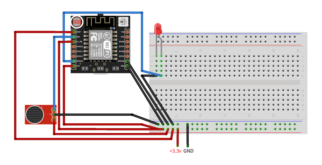
As seen in the breadboard diagram, we want to supply 3.3v to our circuit. We will be using our LED as a connection indicator on pin GPIO13, for this I used a 2-pin rainbow LED but any LED will work here. Next we want to connect our sound detection module, we will use the analog pin connected to our ESP8266 ADC pin. We can connect our LED GND pin, sound detection module GND pin, ESP8266 GND pin and GPIO15 pin to our power supply GND, and our ESP8266 REST pin, CH_PD (EN) pin, VCC and sound module + pin to our power supply +3.3v.
The second circuit we want to build will be the one controlling the LED strip, we’ll call this our client.
The client circuit:
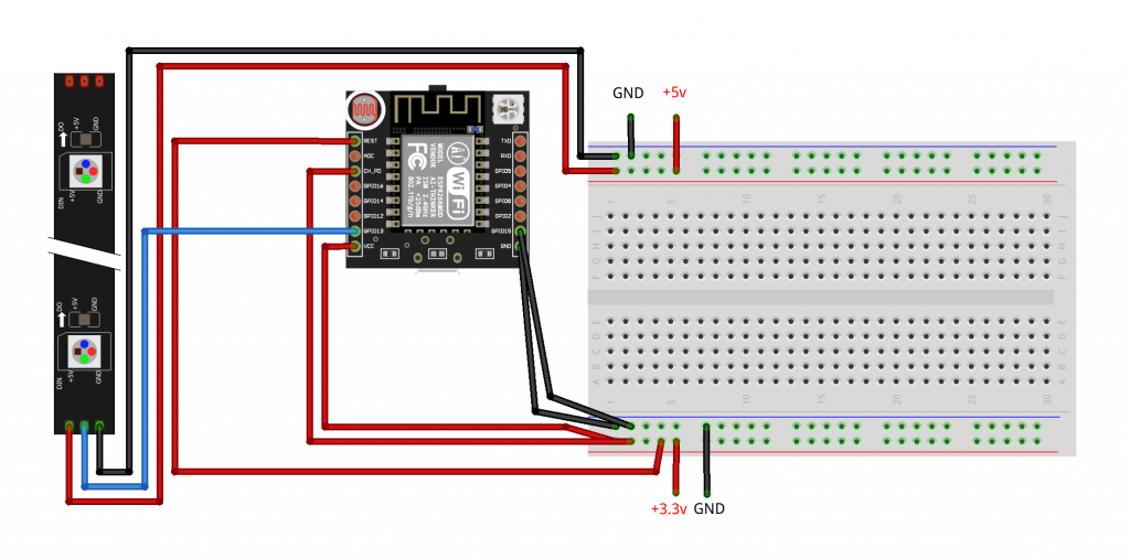
In the client circuit we want to connect our ESP8266 to the +3.3v like we did in the server circuit and add our addressable LED’s to a 5v power supply, we will connect our data in pin (DI) on the LED strip to our GPIO13 pin on our ESP82666.
Conclusion
We should now have two circuits, a server and client.
In part 2 we will start coding the sketches and upload them to our two ESP8266 modules.
Great work.