Part 2: Coding the server ESP8266
Here we will go through the code to run the server and client ESP8266, if you have problems with the circuit setup and connections please see part 1 of this tutorial.
We will use ArduinoOTA for our uploads, if you want to find out more on ArduinoOTA please see ESP8266 OTA Updates with Arduino IDE | Over the Air
The Libraries
First we want to download and install our necessary plugins, to do this, open Arduino IDE and go to Tools and select Manage Libraries or press Ctrl + Shift + I to open the library manager, we then want to search and install the libraries, here is what we’ll need:
#include <ESP8266WiFi.h>
#include <WiFiClient.h>
#include <ESP8266WebServer.h>
#include <ESP8266mDNS.h>
#include <ESP8266HTTPClient.h>
#include <WiFiUDP.h>
#include <ArduinoOTA.h>
Defining our variables
After we are done installing and defining our libraries, we can go ahead and declare the variables we’ll need.
#define BUTTON    14   // Our optional button pin attached to GPIO14
#define MIC_PIN   A0   // Microphone is attached to ADC
#define DC_OFFSET 0    // DC offset in mic signal - if unusure, leave 0
#define NOISE     235  // Noise/hum/interference in mic signal
#define LED_PIN   13   // Connection indicator LED on GPIO13

// Initial red, green and blue values, always between 0 and 255
byte
  selectableR = 255,
  selectableG = 0,
  selectableB = 0;

// Our button press check and operating mode counter
int
  btnCounter = 0,
  countRead = 0;

String page = "<html lang='en'>"; // The initial declaration of our returned html page

MDNSResponder mdns;
ESP8266WebServer server(80);
HTTPClient http;

WiFiUDP UDP;

// The struct we wil use for sending data to our client over UTP
struct led_command {
  uint8_t opmode;
  uint32_t data;
  uint8_t red;
  uint8_t green;
  uint8_t blue;
};
Creating our methods
Now we are ready to start implementing our methods, we will use the setup method to start the WiFi connection, set up the OTA settings, start the UDP connection and also set up our web service endpoints.
void setup() {
  // Check if the button pin was defined
  #ifdef BUTTON
    pinMode(BUTTON, INPUT);
  #endif

  // Declare our LED_PIN as output
  #ifdef LED_PIN
    pinMode(LED_PIN, OUTPUT);
  #endif

  // Begin our serial port
  Serial.begin(115200);

  WiFi.persistent(false);

  // Set our html page content, you can edit this to your liking
  page += "<head>";
  page +=   "<meta http-equiv='refresh' content='60' name='viewport' content='width=device-width, initial-scale=1'/>";
  page +=   "<link rel='stylesheet' href='https://maxcdn.bootstrapcdn.com/bootstrap/3.3.7/css/bootstrap.min.css'/>";
  page +=   "<script src='https://ajax.googleapis.com/ajax/libs/jquery/3.1.1/jquery.min.js'></script>";
  page +=   "<script src='https://maxcdn.bootstrapcdn.com/bootstrap/3.3.7/js/bootstrap.min.js'></script>";
  page +=   "<meta name='viewport' content='width=device-width, initial-scale=1'/>";
  page +=   "<title>Reactive LEDs</title>";
  page += "</head>";
  page += "<body>";
  page +=   "<div class='container-fluid'>";
  page +=     "<div class='row'>";
  page +=       "<div class='col-md-12'>";
  page +=         "<div class='jumbotron' style='text-align: center'>";
  page +=           "<h2>Reactive LEDs Server Running</h2>";
  page +=           "<br/>";
  page +=           "<p>";
  page +=             "<a class='btn btn-primary btn-large' href='+'>Next Effect</a>";
  page +=           "</p>";
  page +=         "</div>";
  page +=       "</div>";
  page +=     "</div>";
  page +=   "</div>";
  page += "</body>";
  page += "</html>";

  // Calling our connect method
  connect();
}

void connect ()
{
  // Disconnect first
  disconnect();

  Serial.printf("wake = %d\n", WiFi.forceSleepWake());
  // Set WiFi properties
  WiFi.mode(WIFI_STA);
  WiFi.hostname("node_server");
  WiFi.begin("ap_name", "ap_password");

  // Wait until WiFi is connected
  while (WiFi.status() != WL_CONNECTED) {
    delay(500);
    Serial.print(".");
  }

  // Start the OTA setup
  ArduinoOTA.onStart([]() {
    String type;
    if (ArduinoOTA.getCommand() == U_FLASH) {
      type = "sketch";
    } else { // U_SPIFFS
      type = "filesystem";
    }

    // NOTE: if updating SPIFFS this would be the place to unmount SPIFFS using SPIFFS.end()
    Serial.println("Start updating " + type);
  });

  ArduinoOTA.onEnd([]() {
    Serial.println("\nEnd");
  });

  ArduinoOTA.onProgress([](unsigned int progress, unsigned int total) {
    Serial.printf("Progress: %u%%\r", (progress / (total / 100)));
  });

  ArduinoOTA.onError([](ota_error_t error) {
    Serial.printf("Error[%u]: ", error);
    if (error == OTA_AUTH_ERROR) {
      Serial.println("Auth Failed");
    } else if (error == OTA_BEGIN_ERROR) {
      Serial.println("Begin Failed");
    } else if (error == OTA_CONNECT_ERROR) {
      Serial.println("Connect Failed");
    } else if (error == OTA_RECEIVE_ERROR) {
      Serial.println("Receive Failed");
    } else if (error == OTA_END_ERROR) {
      Serial.println("End Failed");
    }
  });
  ArduinoOTA.begin();

  // Display WiFi properties
  Serial.println("");
  Serial.println("WiFi connected");
  Serial.println("IP address: ");
  Serial.println(WiFi.localIP());
  Serial.println();
  Serial.print("MAC: ");
  Serial.println(WiFi.macAddress());

  if (mdns.begin("esp8266", WiFi.localIP())) {
    Serial.println("MDNS responder started");
  }

  // This will be your location (http://ip-of-the-server/) and return your page html
  server.on("/", [](){
    server.send ( 200, "text/html", page );
  });

  // Location (http://ip-of-the-server/initial) and return the initial operating mode (btnCounter)
  server.on("/initial", [](){
    server.send ( 200, "text/html", String(btnCounter) );
  });

  // Location (http://ip-of-the-server/+) increments the operating mode (btnCounter)
  server.on("/+", [](){
    server.send( 200, "text/html", page );
    Serial.println("hit");
    if (btnCounter == 5) {
      btnCounter = 0;
    } else {
      btnCounter++;
    }
  });

  // Location (http://ip-of-the-server/next) increments the operating mode (btnCounter)
  server.on("/next", [](){
    if (btnCounter == 5) {
      btnCounter = 0;
    } else {
      btnCounter++;
    }
    server.send( 200, "text/html", String(btnCounter) );
    Serial.println("App: Next effect");
  });

  // Location (http://ip-of-the-server/effect?mode=0) receives the operating mode (btnCounter)
  server.on("/effect", [](){
    btnCounter = server.arg(0).toInt();
    Serial.println("App: Certain Effect");
  });

  // Location (http://ip-of-the-server/color?red=0&green=0&blue=255) sets the rgb values
  server.on("/color", [](){
    selectableR = server.arg(0).toInt();
    selectableG = server.arg(1).toInt();
    selectableB = server.arg(2).toInt();
    Serial.println("App: Color Selected");
  });

  // Location (http://ip-of-the-server/getcolor) get the current rgb values
  server.on("/getcolor", [](){
    server.send( 200, "text/html", String(selectableR) + "," + String(selectableG) + "," + String(selectableB));
    Serial.println("App: Color Retrieved");
  });

  // Start the web server
  server.begin();
  Serial.println("HTTP server started");

  // Start the UDP connection on port 7171
  UDP.begin(7171);
}

void disconnect ()
{
  // Disconnect from WiFi network
  WiFi.disconnect(true);
  Serial.printf("sleep 1us = %d\n", WiFi.forceSleepBegin(1));
}
Finally we will create our loop. The loop will read our pins (sound module and button) and send the operation mode and sound values to the client every 4 seconds, the purpose of the delay is to make sure we give our client enough time to receive and process the values from our server.
void loop() {
  // n will hold our sound data
  int n;

  // If our button is defined, make change the operation mode on press
  #ifdef BUTTON
    if ((digitalRead(BUTTON) == 1) && (countRead == btnCounter)) {
      if (btnCounter == 5) {
        btnCounter = 0;
      } else {
        btnCounter++;
      }
    }
    if (digitalRead(BUTTON) == 0) {
      countRead = btnCounter;
    }
  #endif

  // Handle the web server requests
  server.handleClient();
  // Handle the OTA requests
  ArduinoOTA.handle();

  // Read the mic values on the MIC_PIN and process the values
  n = analogRead(MIC_PIN);                 // Raw reading from mic
  n = abs(n - 512 - DC_OFFSET);            // Center on zero
  n = (n <= NOISE) ? 0 : (n - NOISE);      // Remove noise/hum

  // Here we print the values (can be used to calibrate the sound module)
  Serial.println("Sending sound: " + String(n));
  Serial.println("Sending mode: " + String(btnCounter));

  // Send the processed sound value and operation mode to the client
  sendLedData(n, btnCounter);

  // Check if our connection LED is defined and turn it on or off
  #ifdef LED_PIN
    if (btnCounter < 5) {
      digitalWrite(LED_PIN, HIGH);
    }
  #endif

  if (btnCounter == 5) {
    #ifdef LED_PIN
      digitalWrite(LED_PIN, LOW);
    #endif
  }

  // 4ms delay
  delay(4);
}

void sendLedData(uint32_t data, uint8_t op_mode)
{
  // Create and define the struct we will send to our client over UDP
  struct led_command send_data;
  send_data.opmode = op_mode;
  send_data.data = data;
  send_data.red = selectableR;
  send_data.green = selectableG;
  send_data.blue = selectableB;

  // This will be the IP address of our client
  IPAddress ip(192,168,1,200);
  // Send the packet to our client on port 7001
  UDP.beginPacket(ip, 7001);
  UDP.write((char*)&send_data,sizeof(struct led_command));
  UDP.endPacket();
}
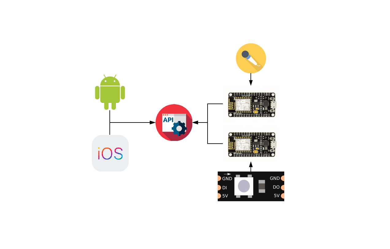
Please note for this project we will be connecting our ESP8266 to a router over WiFi and set the router to assign them specific IP addresses for DHCP. If you do not have a router, you can change the code to set your server ESP8266 as an access point and connect your client to it, you can then give them both IP addresses, with this approach you’ll need to connect your mobile device to your ESP8266 server instead of your router in Part 4.
In Part 3 we will be looking at the code for the client ESP8266, how to handle our addressable LED strip and receiving the UDP packets from the server.
Be First to Comment